
The use of ceramic ceilings in construction in relation to the minimization of thermal bridges in the structure
Publisher
Tisková zpráva
20.10.2008 00:05
Tisková zpráva
20.10.2008 00:05
The use of POROTHERM ceilings - ceramic blocks POT and MIAKO inserts - has long been considered a very quick, simple, and low-demand technology that has been countless times verified over several decades in many constructions. An undeniable advantage is also the fact that this system is part of the complete Porotherm system. Currently, the high fire resistance and lower cost compared to most other ceiling systems are also not negligible. A frequently asked question is the possibility of separating the ceiling structure from the external environment, thereby eliminating thermal bridges.
Crown
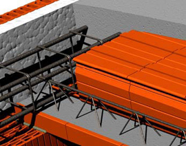
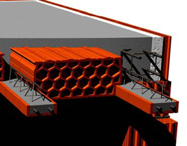
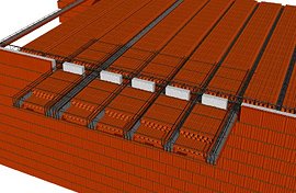
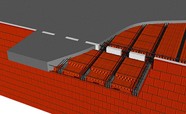
When addressing the issue of thermal bridges in ceiling structures, it is necessary to choose a suitable compromise between the thickness of the inserted thermal insulation and the stability of the masonry. Increasing the thermal insulation is accompanied by a reduction in the length of the ceiling's placement. Therefore, it is necessary to choose the thickness of the insulation in accordance with the width of the masonry. The optimal solution is to use inserted insulation with a thickness of 80 mm in combination with the use of a crown block (80 mm) – Figures 1 and 2 schematically illustrate the method of implementing the ceiling at the location of the POT beams (Figure 1) and in the second direction (parallel to the beams – Figure 2).
In general, it follows from the above that when using more massive masonry, it is possible to use greater thickness of inserted insulation. Thus, the investor's effort to achieve greater insulation capacity by increasing the thickness of the masonry is actually favored.
Crown block
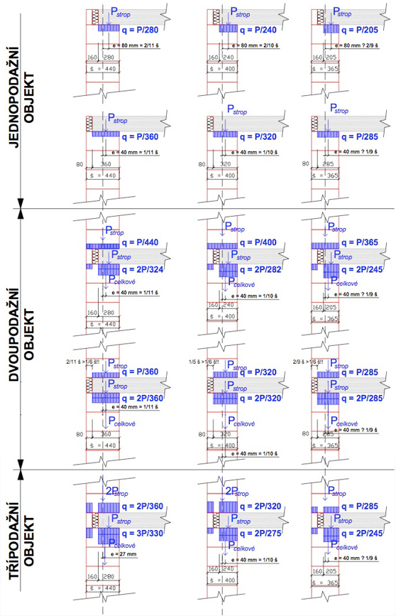
An inseparable part of the optimal solution for connecting the ceiling structure to the external environment is the use of crown blocks. I often encounter the opinion that the use of crown blocks further increases the eccentricity of the loading on the masonry and thus complicates the overall situation. This impression is related to the notion that an 80 mm thick crown block is non-load-bearing and serves only as an element to unify the façade surface and for simpler façade construction. However, this does not correspond to the actual effect of the crown block, since when using only one row of crown blocks, simple buckling can be assumed, and thus actual cooperation in transferring vertical load can occur. The manufacturer of crown blocks, Wienerberger, is aware of this fact and produces crown blocks with a strength of P12. Figure 3 schematically illustrates the possible distribution of stress in the masonry with and without the use of crown blocks. The crown block is considered here as a load-bearing element. The stress distribution is processed for three masonry thicknesses – 440, 400, and 365 mm (in the columns) and for three building variants (single-story, two-story, and three-story buildings). The variant with the crown block is drawn at the top, and the variant without the crown block is drawn below it. From the diagrams, it is evident that the "advantage of reducing eccentricity" by omitting crown blocks practically applies only to single-story buildings; in multi-story buildings, the crown block reduces eccentricity, and it can be stated that with an increasing number of floors, it approaches zero. In the variant without crown blocks, eccentricity remains constant. However, it should be emphasized that this considered single-story object does not occur in practice, as there is always a load from the roof structure transmitted through the crown, or possibly also from an upper wall. In a typical gable roof, the perimeter wall is additionally subjected to horizontal force, further utilizing the crown block ("leans" on it). It is even worth noting that by omitting the crown block, the wall is cantilevered by more than 1/6 of the thickness of the masonry, and thus such a wall should be assessed by static calculation (risk of tension in the bed joint).
Balconies
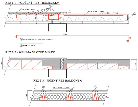
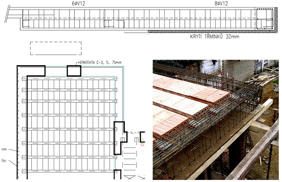
Currently, balconies are often used in building constructions. It is obvious that in this case, the ceiling structure is extended beyond the perimeter wall and cantilevered. In addition to the necessity to reinforce the structure to transfer the negative moment, there is also the problem of thermally insulating the outer balcony structure from the interior. This can be achieved either by "wrapping" the balcony cantilever structure or by inserting thermal insulation into the interface between the indoor and outdoor environment, or a combination of both. By inserting thermal insulation between the beams, sufficient elimination of thermal bridge is achieved, which meets the requirements of AMENDMENT Z1 of ČSN 73 0540 from June 2005 (evaluation by Ing. Šála from August 2005). The method of constructing such a balcony is apparent from the attached sections (Figure 12). The specified dimensions of reinforcement relate to the solution of a specific balcony and are provided here only to clarify the static solution. For individual cases, reinforcement must always be designed and assessed separately. With the appropriate combination of MIAKO inserts, it is also possible to achieve a lower height of the balcony than the ceiling (in the given example, the difference was 40 mm – based on the ceiling height, a difference of up to 100 mm could be achieved). This solution provides the opportunity to more easily and naturally ensure a lower level of the balcony's top layer compared to the floor indoors. It is not necessary to create steps in front of the balcony doors or solve everything with some other complex structural adjustment.
Figure 5 shows the arrangement of the balcony structure before concrete pouring, and Figure 6 shows it after pouring.
That POROTHERM ceilings can also realize demanding structures while minimizing thermal bridges is evidenced by the variant of the corner balcony. In the framework of technical assistance to our customers, I resolved the corner balcony of an apartment building in Brno with my colleague Ing. Navara (Atelier DNA s.r.o., Č.Budějovice). Usually, this structure is resolved with a monolithic reinforced concrete slab, with all the problems of thermal bridges. Therefore, our proposal aimed primarily at achieving minimization of thermal bridges while simultaneously striving for a simple construction solution (elimination of formwork at height, etc.). The result of the design is a corner balcony “inserted” into a steel structure (which can be produced off-site). Thus, an independent balcony structure was created that can be easily insulated by inserting thermal insulation between the balcony and the masonry. After the concrete pouring in the interior is complete, the installation of the outer part of the steel structure (i.e., in the scope of the balcony) will be carried out. Given the load on the inner part of the steel structure from the concrete, sufficient stability of the structure can be anticipated when installing beams without the need for special measures to ensure stability. There are only two thermal bridges here, located where the outer steel beams pass through. For a better understanding, the structure is schematically modeled in Figures 7 and 8.
To realize the column under the corner balcony with a minimum of thermal bridges, it would be possible to adopt the variant of the corner column as we jointly designed with Ing. Navara for the family house with a corner window (Figures 9 and 10). The column (proposed square tube 80/8) is located in the interior and will be clad with wooden paneling, to which the window frames will extend. The investor expressed a desire for a uniform façade surface (ceramics). Therefore, a reinforced concrete beam was chosen as the load-bearing element, with thermal insulation around the perimeter in contact with the external environment. The beam is placed on the column through a steel "box," which is thermally insulated all around with inserted thermal insulation. On the exterior side, ceramic lintels are screwed into this box with stainless steel screws, again over inserted thermal insulation. Between ceramic lintels and the reinforced concrete beam, thermal insulation has, of course, been inserted again throughout the height. The complete "wrapping" can be seen in the photograph (Figure 10), where the construction of the ceramic ceiling is already completed.
If necessary, it is, of course, possible to realize a corner window even without a column. An example of such a construction is evident from the cut of the floor plan and the photograph in Figure 11.
Ing. Ivo Petrášek,
Wienerberger brick industry, a.s.
Plachého 388/28
37046 České Budějovice
telephone: +420 387 766 324
mailto: ivo.petrasek@wienerberger.com
www.porotherm.cz
Crown
When addressing the issue of thermal bridges in ceiling structures, it is necessary to choose a suitable compromise between the thickness of the inserted thermal insulation and the stability of the masonry. Increasing the thermal insulation is accompanied by a reduction in the length of the ceiling's placement. Therefore, it is necessary to choose the thickness of the insulation in accordance with the width of the masonry. The optimal solution is to use inserted insulation with a thickness of 80 mm in combination with the use of a crown block (80 mm) – Figures 1 and 2 schematically illustrate the method of implementing the ceiling at the location of the POT beams (Figure 1) and in the second direction (parallel to the beams – Figure 2).
|
|
In general, it follows from the above that when using more massive masonry, it is possible to use greater thickness of inserted insulation. Thus, the investor's effort to achieve greater insulation capacity by increasing the thickness of the masonry is actually favored.
Crown block
An inseparable part of the optimal solution for connecting the ceiling structure to the external environment is the use of crown blocks. I often encounter the opinion that the use of crown blocks further increases the eccentricity of the loading on the masonry and thus complicates the overall situation. This impression is related to the notion that an 80 mm thick crown block is non-load-bearing and serves only as an element to unify the façade surface and for simpler façade construction. However, this does not correspond to the actual effect of the crown block, since when using only one row of crown blocks, simple buckling can be assumed, and thus actual cooperation in transferring vertical load can occur. The manufacturer of crown blocks, Wienerberger, is aware of this fact and produces crown blocks with a strength of P12. Figure 3 schematically illustrates the possible distribution of stress in the masonry with and without the use of crown blocks. The crown block is considered here as a load-bearing element. The stress distribution is processed for three masonry thicknesses – 440, 400, and 365 mm (in the columns) and for three building variants (single-story, two-story, and three-story buildings). The variant with the crown block is drawn at the top, and the variant without the crown block is drawn below it. From the diagrams, it is evident that the "advantage of reducing eccentricity" by omitting crown blocks practically applies only to single-story buildings; in multi-story buildings, the crown block reduces eccentricity, and it can be stated that with an increasing number of floors, it approaches zero. In the variant without crown blocks, eccentricity remains constant. However, it should be emphasized that this considered single-story object does not occur in practice, as there is always a load from the roof structure transmitted through the crown, or possibly also from an upper wall. In a typical gable roof, the perimeter wall is additionally subjected to horizontal force, further utilizing the crown block ("leans" on it). It is even worth noting that by omitting the crown block, the wall is cantilevered by more than 1/6 of the thickness of the masonry, and thus such a wall should be assessed by static calculation (risk of tension in the bed joint).
 |
| Figure 3 |
Balconies
Currently, balconies are often used in building constructions. It is obvious that in this case, the ceiling structure is extended beyond the perimeter wall and cantilevered. In addition to the necessity to reinforce the structure to transfer the negative moment, there is also the problem of thermally insulating the outer balcony structure from the interior. This can be achieved either by "wrapping" the balcony cantilever structure or by inserting thermal insulation into the interface between the indoor and outdoor environment, or a combination of both. By inserting thermal insulation between the beams, sufficient elimination of thermal bridge is achieved, which meets the requirements of AMENDMENT Z1 of ČSN 73 0540 from June 2005 (evaluation by Ing. Šála from August 2005). The method of constructing such a balcony is apparent from the attached sections (Figure 12). The specified dimensions of reinforcement relate to the solution of a specific balcony and are provided here only to clarify the static solution. For individual cases, reinforcement must always be designed and assessed separately. With the appropriate combination of MIAKO inserts, it is also possible to achieve a lower height of the balcony than the ceiling (in the given example, the difference was 40 mm – based on the ceiling height, a difference of up to 100 mm could be achieved). This solution provides the opportunity to more easily and naturally ensure a lower level of the balcony's top layer compared to the floor indoors. It is not necessary to create steps in front of the balcony doors or solve everything with some other complex structural adjustment.
 |
| Figure 4 Thermal insulation of balconies by inserting thermal insulation |
Figure 5 shows the arrangement of the balcony structure before concrete pouring, and Figure 6 shows it after pouring.
|
|
That POROTHERM ceilings can also realize demanding structures while minimizing thermal bridges is evidenced by the variant of the corner balcony. In the framework of technical assistance to our customers, I resolved the corner balcony of an apartment building in Brno with my colleague Ing. Navara (Atelier DNA s.r.o., Č.Budějovice). Usually, this structure is resolved with a monolithic reinforced concrete slab, with all the problems of thermal bridges. Therefore, our proposal aimed primarily at achieving minimization of thermal bridges while simultaneously striving for a simple construction solution (elimination of formwork at height, etc.). The result of the design is a corner balcony “inserted” into a steel structure (which can be produced off-site). Thus, an independent balcony structure was created that can be easily insulated by inserting thermal insulation between the balcony and the masonry. After the concrete pouring in the interior is complete, the installation of the outer part of the steel structure (i.e., in the scope of the balcony) will be carried out. Given the load on the inner part of the steel structure from the concrete, sufficient stability of the structure can be anticipated when installing beams without the need for special measures to ensure stability. There are only two thermal bridges here, located where the outer steel beams pass through. For a better understanding, the structure is schematically modeled in Figures 7 and 8.
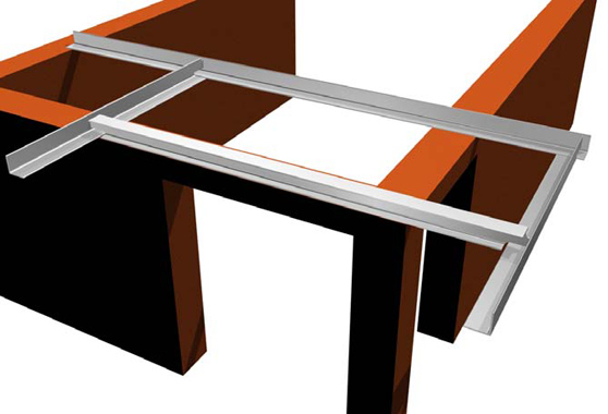 |
| Figure 7 Steel structure of the corner balcony before the installation of beams |
 |
| Figure 8 Structure of the corner balcony after the installation of POT beams and MIAKO inserts |
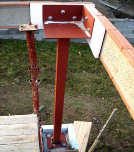
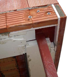
To realize the column under the corner balcony with a minimum of thermal bridges, it would be possible to adopt the variant of the corner column as we jointly designed with Ing. Navara for the family house with a corner window (Figures 9 and 10). The column (proposed square tube 80/8) is located in the interior and will be clad with wooden paneling, to which the window frames will extend. The investor expressed a desire for a uniform façade surface (ceramics). Therefore, a reinforced concrete beam was chosen as the load-bearing element, with thermal insulation around the perimeter in contact with the external environment. The beam is placed on the column through a steel "box," which is thermally insulated all around with inserted thermal insulation. On the exterior side, ceramic lintels are screwed into this box with stainless steel screws, again over inserted thermal insulation. Between ceramic lintels and the reinforced concrete beam, thermal insulation has, of course, been inserted again throughout the height. The complete "wrapping" can be seen in the photograph (Figure 10), where the construction of the ceramic ceiling is already completed.
|
|
If necessary, it is, of course, possible to realize a corner window even without a column. An example of such a construction is evident from the cut of the floor plan and the photograph in Figure 11.
 |
| Figure 11 Structure of the corner window without a column |
Ing. Ivo Petrášek,
Wienerberger brick industry, a.s.
Plachého 388/28
37046 České Budějovice
telephone: +420 387 766 324
mailto: ivo.petrasek@wienerberger.com
www.porotherm.cz
The English translation is powered by AI tool. Switch to Czech to view the original text source.