

AV-School, Educational building for audio-visual studies

 |
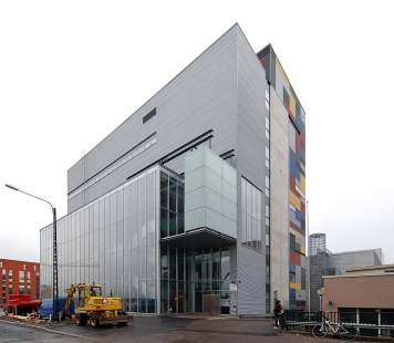
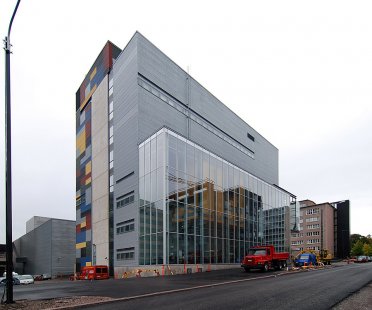
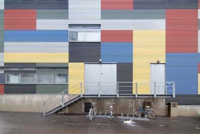
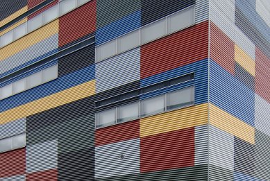
The building is a workshop that provides secondary education to students who are under twenties. The material and colour environment of the building has been adapted to reflect their image of the world: consciously relaxed and supporting creativity. The selection of materials includes thin gauge steel sheet in its various forms, smooth, corrugated and perforated; untreated concrete as blockwork or cast structures; as well as plywood with a translucent finish in various shades.
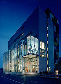
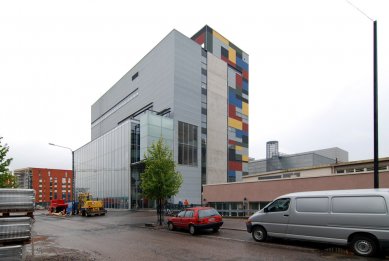
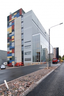
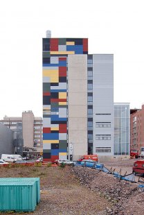
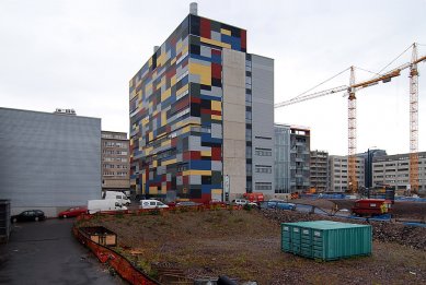
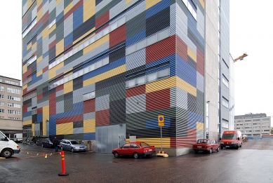
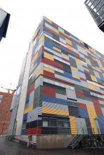
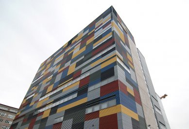
The design of the rear facade was inspired by the colourful and constantly changing piles of containers stored in the neighbourhood. The coloured wall was deliberately located on the side of the service yard, where it glistens, mostly in small fragments, into the environment. The container theme becomes the key principle of space arrangement also in the four-storey tall lobby, with the coloured plywood containers used for visual inter-connection of the floors and when illuminated, to create an attractive welcome to the building. The building is alive 24 hours a day. The common and open spaces are located in a four-storey high arrangement behind the glass display window. The display case radiates energy into its environment and reflects the open and dynamic nature of the activities. In order to clarify the functional concept of the building, and to keep the division of masses as simple and delicate as possible, the building has been divided into longitudinal zones. Each zone has its own unique character, realised with different materials and colours.
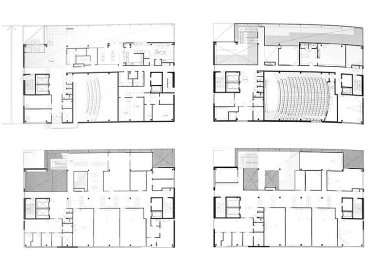
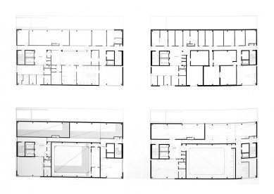
The project schedule was extremely tight. From the first contacts, the planning and the construction was completed within 14 months. For this reason, a steel frame became a very natural choice at a very early stage of the planning, particularly since it became obvious as the space planning progressed that almost every intermediate floor would be different, due to the large openings.
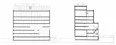
In the longitudinal direction of the building, a modular spacing of 5.4 m was selected, as it matched the facades and the openings on the levels. In the horizontal direction, the modular spacing is 4.8-7.2-12.0 m. The basic floor height is 3.6 m, but there are several two-storey tall spaces in the building, and the impressive entrance lobby is four storeys tall. The total number of floors above ground is nine, with the top air conditioning plant floor also adapted to the same frame. Excavation work was minimised due to difficult ground conditions, which is why the basement is only partly below the ground. The foundations of the buildings consist of driven reinforced concrete piles.
The basic building frame comprises square hollow section columns of composite construction and low HQ beams in the intermediate floors. The intermediate floors are hollow core slab elements, with a thickness varying from 265 to 400 mm, depending on the span and the loads.
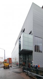
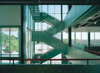
Other steel structures include the frames of the tall glass walls, the cantilevered canopy over the main entrance, partly suspended with tension rods, and the various steel staircases and railings. The flexibility of the steel frame is reflected in slim and low structures, and easy joints. The steel frame also facilitates excellent dimensional accuracy of parts connected with the facade.
The stiffening of the frame is realised with stairwells and lift wells located on the end walls and built of reinforced concrete elements. The bottom parts of the wells were post-stressed vertically to improve stability. The intermediate floors act as a plate structure in horizontal direction.
The dimensioning of the composite columns was carried out using the COMCOL software developed by Rautaruukki and Fundia, taking into consideration fire dimensioning of the second order. The HQ beams were dimensioned using appropriate calculation software. The bottom flanges of the beams have a fireproof paint finish or suitable fireproof plate cladding. A more accurate 3D calculation with the FEM software was required for the steel structures of the entrance canopy, to ensure proper management of deformation of the long cantilevers and of the stability of the entire system. The calculations were performed using the FEM-Design software developed by Skanska. The point-like fixing of the glass structures also made it necessary to perform a more detailed stress analysis. This was realised using the STAAD software.
Teräsrakenne, 4/2002


0 comments
add comment